Installer portal
 Solar Academy
 Download
 Solar Terminal


KOSTAL Multi Device Control (MDC)
The smart solution for PV systems with multiple inverters
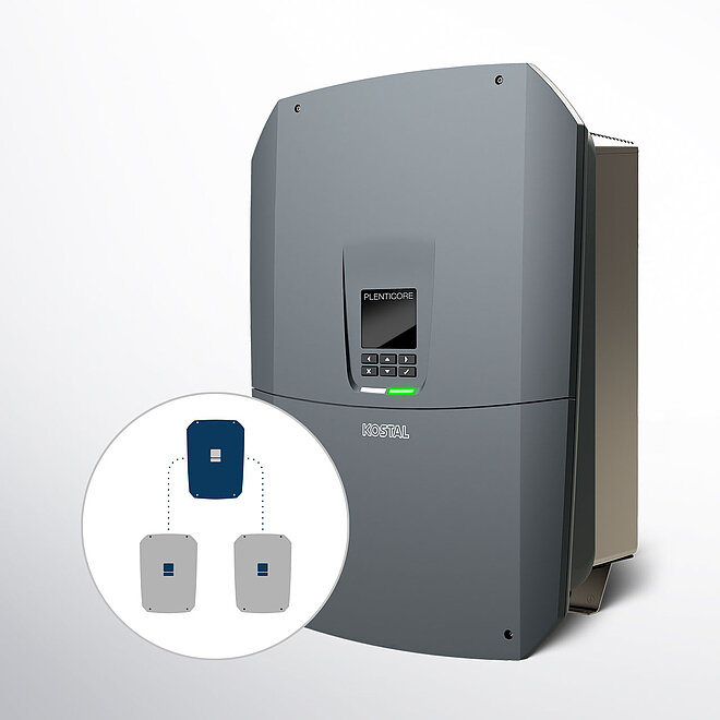
Challenging roof surfaces or high storage requirements? With the new Multi Device Control (MDC) for the PLENTICORE G3, you can implement complex PV projects more easily and efficiently than ever before. Control up to three inverters centrally via a single device and save valuable time during installation and configuration.
Multi Device Control is currently available exclusively for the PLENTICORE G3 and PLENTICORE MP G3. The feature is being continuously developed and will support further compatible devices in the future.
The benefits of MDC
- Centralised control: A PLENTICORE G3 acts as an MDC host and handles the complete control and monitoring of all MDC-compatible devices on the home network
- Efficient commissioning: Forget the tedious process of configuring each device individually in KSEM. Clients are integrated directly and intuitively via the device manager on the MDC host’s web server
- Flexible battery management:
- By default, one battery storage unit can be controlled via the host
- A maximum of 3 inverters with a connected battery can be used in the device network.
- Optimal storage strategy: The system intelligently adjusts the charging and discharging power to the respective capacity in order to achieve a uniform SoC (State of Charge) across all storage units
- Future-proof & compliant: The MDC host distributes signals for load shedding (in accordance with Section 9 EEG or Section 14a EnWG) directly to all clients and supports modern requirements such as dynamic electricity tariffs
- Everything at a glance: The power flow diagram of the entire system is clearly visualised on the display or on the MDC Host’s web server
Note: To operate more than one battery in the MDC system, the paid product extension “Battery Control with MDC” is required. In backup mode, only the battery connected to the MDC host is used.
KOSTAL Practical Tip
Where MDC makes the difference
The ‘three-roof scenario’: Do you have a project with east, west and south-facing roofs? Instead of complicated wiring, use three PLENTICORE G3 units in an MDC network. A host controls the entire system, whilst the clients efficiently feed energy from the various roof areas into the grid
Maximum self-sufficiency for energy-intensive projects: For customers with extremely high night-time consumption or heat pumps, a single battery is often insufficient. With MDC and the corresponding extension, you can combine three inverters, each with a battery, into an XL storage system. Best of all: the host ensures that all batteries operate in sync
Sector coupling with dynamic tariffs: Use MDC to make your system fit for the energy world of tomorrow. Thanks to the host’s central control, dynamic electricity tariffs can be optimally utilised to charge the batteries in the network cost-effectively
MDC installation: How it works
- Hardware setup: Install all inverters and the energy meter (KEM or KSEM) at the grid connection point
- Networking: Connect the host to the meter via RS485 and all devices to each other via LAN (Wi-Fi is not permitted for MDC communication)
- Configuration: During initial setup, define one PLENTICORE G3 as the host and the others as clients
- Go-live: Activate data transmission to the KOSTAL Solar Portal to manage the entire system in a single overview
MDC with PLENTICORE G3: Find out more now
Take advantage of the MDC function from software version 3.06.10 onwards and
see just how easy plant design can be today.
Download the technical data sheet now Arrange a training session now
FAQ: Battery Management with MDC
Specifically, the PLENTICORE inverters in the G3 series have been approved as MDC hosts.
Based on the available sources, this includes the following models:
- PLENTICORE G3
- PLENTICORE MP G3
Important requirements for the MDC host:
- Software version: The function is available from software version 3.06.10 onwards
- Configuration: A G3 inverter must be configured as an MDC host during initial setup
- Additional components: An authorised energy meter (KEM or KSEM) must be connected to the MDC host via the RS485 interface
- Battery logic: If a battery is present in the system, the battery with the largest usable capacity must be connected to the MDC host
Note: Earlier device generations such as the PLENTICORE plus / G2, PLENTICORE BI / G2 or the PIKO series are not approved as MDC hosts (nor as clients).
Currently, only the following devices from the PLENTICORE G3 series are approved for use as MDC clients:
- PLENTICORE G3
- PLENTICORE MP G3
These devices can be integrated into the system as clients in both battery-powered and non-battery-powered versions.
Important technical requirements:
- Software version: For the control system to function, software version 3.06.10 or higher must be installed on all participating devices (host and clients)
- Number: An MDC network can consist of a maximum of one host and two MDC client inverters
- Configuration: The device is designated as an MDC client during initial commissioning or subsequently via the “Change operating mode” menu on the respective device
Note: Earlier models such as the PLENTICORE plus / G2, PLENTICORE BI / G2 or devices from the PIKO series are expressly not approved for MDC and can only be managed via the conventional KSEM control system. Parallel control via MDC and KSEM is not permitted.
The key difference between an MDC host and an MDC client lies in the distribution of control roles: the host acts as the ‘brain’ of the system, whilst the clients carry out the host’s instructions.
Here are the differences in detail:
Control and monitoring function
- MDC host: It handles the central monitoring and control of all MDC-compatible devices on the home network. It manages the device manager, through which clients are searched for and integrated. Furthermore, only the host displays the power flow diagram of the entire system
- MDC client: It is controlled by the host. The web server or a client’s display shows only the current readings of the respective device, not those of the entire system
Connection to peripheral devices
- MDC Host: This is the only device connected directly to the energy meter (KEM or KSEM) via the RS485 interface. External signal components such as district heating control receivers or control boxes (§14a EnWG) are also connected exclusively to the host
- MDC client: It does not communicate directly with the meter or the control box, but receives all relevant data and control signals from the host via the LAN connection
Battery management and backup
- MDC Host: It controls the battery charging strategy for the entire network. If multiple batteries are used, the battery with the highest capacity must be connected to the host. In backup mode (emergency power), only the battery connected to the host is used
- MDC client: For clients with a battery, only the individual state of charge (e.g. min. SoC) can be set; overarching battery settings are configured centrally on the host. In backup mode, all client inverters are switched off
System configuration
- MDC Host: This is where the power limits (e.g. 60% feed-in limit) for the entire system are configured. It can also serve as an internet bridge for the clients
- MDC client: The Modbus protocol is enabled by default so that the host can read data from it. A Wi-Fi connection to the host is not permitted for clients; they must be connected via LAN
EEBus
- MDC host: The host must be connected to the EEBus counterpart
- MDC client: All clients must be connected to the EEBus counterpart
The use of Multi Device Control (MDC) offers several significant advantages over conventional control via the KOSTAL Smart Energy Meter (KSEM), particularly when integrating storage systems and meeting modern regulatory requirements:
- Multiple battery storage units: The most important advantage is the number of batteries that can be controlled. Whilst the KSEM control system supports only one device with a battery, MDC enables the control of up to three devices with connected batteries (provided the relevant product extension is active on the host)
- Support for dynamic electricity tariffs: MDC is designed for the use of dynamic electricity tariffs, a function which, according to sources, is not offered by the KSEM
- Modern grid control (Section 14a EnWG): MDC supports power limitation in accordance with Section 9 EEG and Section 14a EnWG in conjunction with an FNN control box. The MDC host receives the signals (e.g. from a remote control receiver) and actively distributes them to all MDC clients to ensure correct regulation of the entire system.
- Centralised visualisation: The power flow diagram of the entire system is clearly displayed directly on the screen and on the MDC host’s web server. With KSEM control, all inverters previously had to be entered individually into the KSEM
- Simplified configuration: The client inverters are integrated intuitively via the device manager in the MDC host’s web server. This eliminates the need for manual setup of each individual inverter in the KSEM
- Intelligent charge management: MDC automatically activates the storage of surplus AC energy from local generation. This means that the host utilises the energy from all PV inverters present in the domestic grid to charge the battery system. Furthermore, the host ensures SoC (State of Charge) balancing between the various batteries in the network
- Number of batteries: An MDC system network can comprise a maximum of three inverters, each with one connected battery (one MDC host and two MDC clients)
- Requirement for multiple storage units: To operate more than one battery in the network, the paid product extension “Battery Control with MDC” must be activated on the MDC host inverter. Without this extension, only one battery can be operated on the MDC host
- Rule for capacity distribution: The battery with the largest usable capacity must be connected to the MDC host inverter
- Management of different capacities: The system supports batteries with different storage capacities. The MDC host dynamically adjusts the charging and discharging power to the respective capacity in order to balance the state of charge (SoC) between the batteries
The technical implementation of battery control in a system with multiple storage units is handled by Multi Device Control (MDC). In this setup, a central unit coordinates the entire network.
Here are the technical details on how it works:
System architecture and role allocation
An MDC system consists of a maximum of one MDC host (a PLENTICORE G3 inverter) and up to two MDC clients.
- Central control: The MDC host handles the complete monitoring and control of all MDC-compatible devices in the home network
- Hardware requirements: To operate more than one battery in the system, the paid product extension “Battery control with MDC” must be activated on the MDC host. Without this extension, only one battery can be operated on the host itself
- Battery placement: The battery with the largest usable capacity must be connected to the MDC host inverter
Charging strategy and SoC management
The system is designed to balance the storage charge levels (SoC – State of Charge) between the devices:
- Power adjustment: If the batteries have different capacities or set minimum SoCs, the host dynamically adjusts the charging and discharging power to the respective capacity
- Synchronisation: The aim is to achieve a uniform SoC across all batteries
- The 5% buffer: For technical reasons, there is a 5% difference between the host and clients. The MDC host, with its battery, is always the last device to reach full charge (100% SoC) and also the last to reach the minimum SoC
- AC charging: The host automatically utilises the energy from all PV inverters in the home network to charge the entire battery system
Communication and sensors
- Data connection: Communication between the host and clients must take place via LAN; a Wi-Fi connection is not permitted for the MDC control system
- Energy metering: The energy meter (KEM or KSEM) is installed at the grid connection point and connected directly to the MDC host via an RS485 interface. The host then distributes the information and control signals (e.g. for load shedding) to the clients
Special features during operation
- Backup operation: In the event of a mains failure, only the battery connected to the MDC host is used in backup mode. All client inverters (and their batteries) are switched off in this mode.
- Configuration: Common settings for battery usage are configured centrally on the MDC host’s web server and apply to all clients. Only the individual state of charge (e.g. minimum SoC) is configured on the clients themselves.
- Battery control with MDC is a paid product extension [1 x PLENTICOIN]
- It must be purchased and activated on the MDC host inverter if more than one battery (up to three) is to be used in the MDC system network
- Without this extension, only one battery can be connected to and controlled via the MDC host inverter
Good to know: Battery function and battery management with MDC
Two functions – two different roles:
although the two terms sound similar, they fulfil completely different roles within the system. It is important to distinguish clearly between them when planning, designing and expanding your solar panel system.